Conventional layerwise cycle
Cure→Separate→Recoat→Reset
Repeat the sequence for the next layer.
Conventional layerwise SLA process animation.3D Printing Systems Engineering
Continuous rotation. Scalable exposure.
A new path for resin replenishment.
I developed rotational, helical 3D printing to address three connected bottlenecks: build size, stop-and-start processing, and material delivery. The goal was to make a wider range of useful parts—not just print the same parts faster.
Explore the system ↓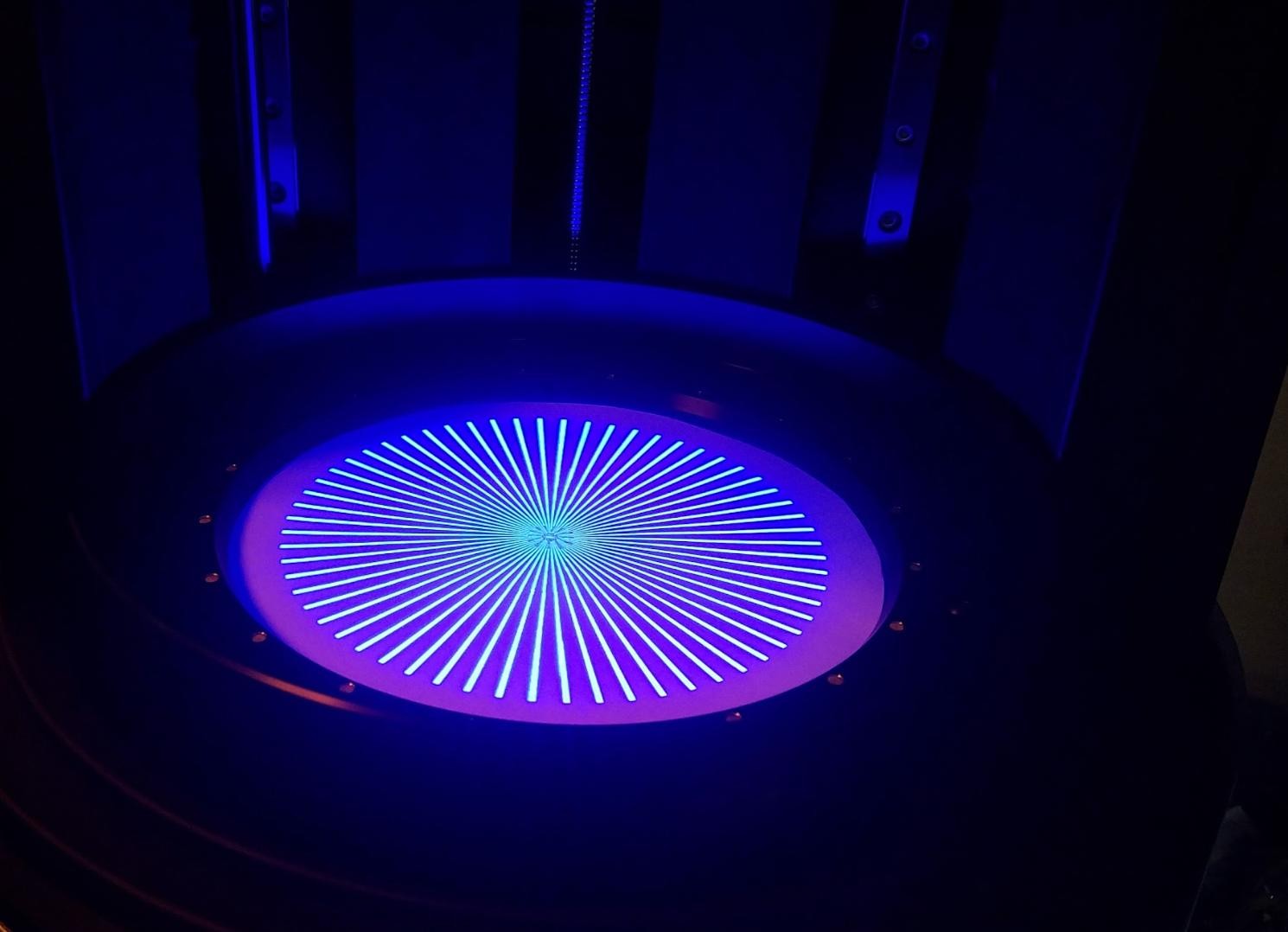
Inventor: Kurt Dudley · Two foundational U.S. patents
Conventional layerwise vat printing repeatedly pauses for exposure, separation, recoating, and repositioning. My approach distributes those functions around a rotating build surface. Different regions can cure and replenish at the same time, while synchronized vertical motion builds a helical path.
Repeat the sequence for the next layer.
Conventional layerwise SLA process animation.Spatially separated functions operate together.
Rotation + exposure + vertical motion stay synchronized.
10 layers/s Prototype demonstration rate reported by Kurt.
Watch the ring and rectangular print demonstrations below. Rate depends on the geometry, material, dose, and machine configuration.
The machine rotates. The part does not have to be round.
Continuous motion only helps if the material can keep up.
In inhibition-based continuous printing, an uncured interfacial region helps keep the growing part from adhering to the window. Resin still has to reach the active interface. Viscosity, flow distance, and the exposed cross-section affect how quickly it can replenish.
My system combines inhibition with polarly arranged cure zones and dedicated resin channels. As the build surface rotates, each region passes through a replenishment channel before returning to an exposure zone.
The engineering objective: replenish dense cross-sections without relying only on resin flowing inward from the outer edge.
This architecture is intended to reduce the dependence of continuous printing on open lattice geometry and to broaden the usable material window. Actual speed remains a function of resin rheology, cure dose, channel geometry, and motion control.
Carbon’s US10589512B2 discusses K. Dudley and WO2014165265A1, the international spiral-buildup disclosure. It describes rotation as assisting resin delivery and separately discusses viscosity and dense cross-sections as factors in fabrication speed.
The patent also distinguishes its CLIP arrangements from my disclosure. This is documented technical consideration of my work in a closely related problem area, rather than evidence of commercial adoption.
Fabbaloo reports on Orange Maker’s Heliolithography process.
Read the contemporaneous report ↗The provisional filing date claimed by Carbon’s subsequent rotation patent.
Read “Related applications” ↗The eight-day interval compares press coverage with a provisional filing—not two patent publication dates. The international spiral-buildup disclosure was published October 9, 2014. Timing alone does not establish why Carbon filed or when it considered my work.
Rotational scanning sweeps a localized exposure field across a larger build envelope. The aim is to preserve fine projected detail while expanding the area that can be addressed, rather than simply enlarging every projected pixel.
Conceptual plan views: cyan indicates exposure sectors; dark regions indicate spaces between sectors. Not machine dimensions or a performance simulation.
Ceramic-loaded resins demand a process that can handle challenging flow behavior. Rotation can help manage that material—but what rotates determines whether it also expands the area available for printing.
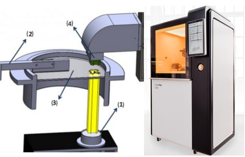
A rotating vat and wiper blade provide fresh ceramic slurry for layerwise exposure. The build platform moves vertically; vat rotation does not itself sweep the part through a larger exposure envelope.
Rotation’s role: material distribution.
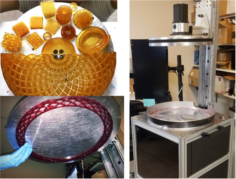
My architecture rotates the build surface through localized exposure sectors and resin replenishment regions. This provides a route to addressing a larger swept area with the same localized light source and fine projected pixel size.
Rotation’s role: material transport + area coverage.
Images extracted from my comparison slide. The Orange Maker specimens illustrate build-area concepts; they are not presented as qualified ceramic casting cores. This compares process architecture, not measured speed or build size across all Lithoz models.
My development focus is to combine rotational scanning with controlled delivery of highly loaded resin. A larger swept envelope could support longer cores or more cores per build, subject to usable radius, exposure dose, slurry behavior, and dimensional control. Ceramic filling, curing, debinding, and sintering must be developed together.
Process references: Lithoz LCM recoating description ↗ · Lithoz technology overview ↗
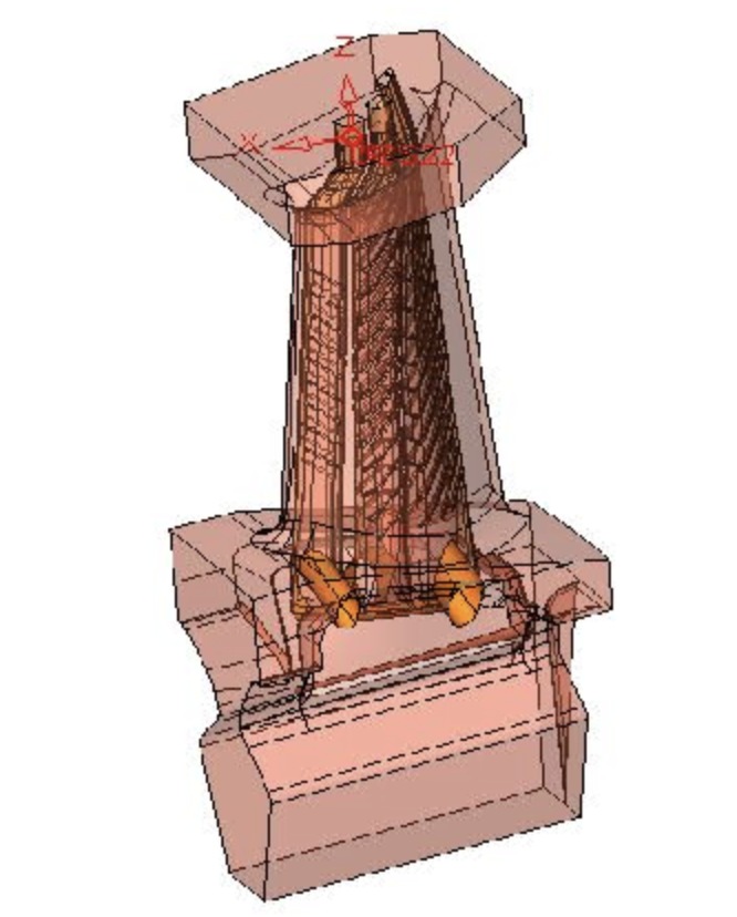
Ceramic cores for blades and vanes in gas turbines used for power generation.
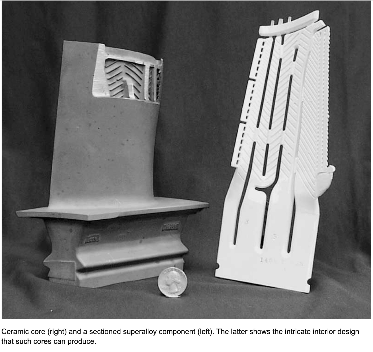
Investment casting uses ceramic cores to define internal cavities in metal components. After casting and core removal, those spaces become the cooling passages that allow turbine blades and vanes to operate in demanding thermal environments.
For me, this is a compelling application of additive manufacturing: use digital design to make complex core geometry, then connect it to a proven metal-production process.
The opportunity is to develop the ceramic core and its manufacturing process together—connecting cooling geometry, printability, and casting requirements.
Printed ceramic cores are already an established industry direction. Lithoz documents silica-based cores for nickel-alloy turbine-blade casting, and Safran has installed Lithoz systems for casting-core production. My opportunity is to investigate how rotational processing can extend the usable build envelope and material-processing options.
Sources: Lithoz casting-core materials ↗ · Safran casting-core production ↗ · GE Vernova Q2 2026 ↗ · GE Vernova January 2026 call ↗
Explore ceramic materials & process development →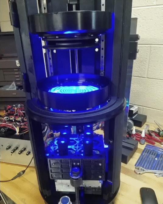
My work connects machine design to the chemistry and mechanics of making a part. Mechatronics synchronization aligns rotation, vertical motion, exposure timing, and resin delivery.
Coordinating multiple tiled projectors offers a route to increasing available optical power across the cure zones while scaling the addressed area. Exposure calibration, tile registration, and synchronized motion are essential to maintaining consistent dose and geometry.
Replenishment channels and rotational transport create a path to processing more demanding formulations, including highly loaded ceramic resins. This connects the printing system to my broader work in technical ceramic tooling and advanced materials.
Scalability is a system question: can light delivery, material flow, and motion remain coordinated as the machine grows?
Discuss custom systems & process development →| Architecture | How material reaches the process | My design focus |
|---|---|---|
| Inhibition-based continuous printing Including Carbon CLIP | An inhibition region separates the growing part from the window; resin replenishes the curing interface. | Add dedicated channels and rotational transport to address replenishment across dense sections and more viscous formulations. |
| Layerwise ceramic vat printing Including Lithoz LCM | Ceramic slurry is dispensed onto a transparent vat; a vertically moving platform is exposed layer by layer. | Rotate the build surface through a localized exposure field to address a larger swept area with fine projected detail. |
| My rotational / helical architecture | Repeated cure zones and replenishment channels operate around the rotating build surface. | Co-design build area, dose, flow, and continuous motion for the target part and material. |
These are architectural distinctions, not head-to-head performance results. Carbon produces solid parts as well as lattices. Lithoz offers multiple build sizes and resolutions. Material compatibility and throughput require validation for each configuration.
Prototype descriptions, images, and demonstration rate provided by Kurt Dudley. Patent records document the inventions; they do not independently validate prototype performance.