01 / Understand
Follow the workflow.
Look at what people need to accomplish, where manual labor accumulates, and what limits throughput.
Explore the systems, materials, and workflows behind my approach to additive manufacturing and scalable production.
The opportunity is often bigger than the printed part. It can be a manual task, a tooling delay, or a design workflow that prevents a good idea from becoming a viable product.
Look at what people need to accomplish, where manual labor accumulates, and what limits throughput.
Use complex geometry, rapid tooling, or application-specific materials where they offer a meaningful advantage.
Develop the geometry, material, hardware, and post-processing around the same manufacturing requirements.
Build a path to repeatable production, combining additive and conventional manufacturing as volumes grow.
From automating laboratory workflows to accelerating composite tooling and making customized designs manufacturable.
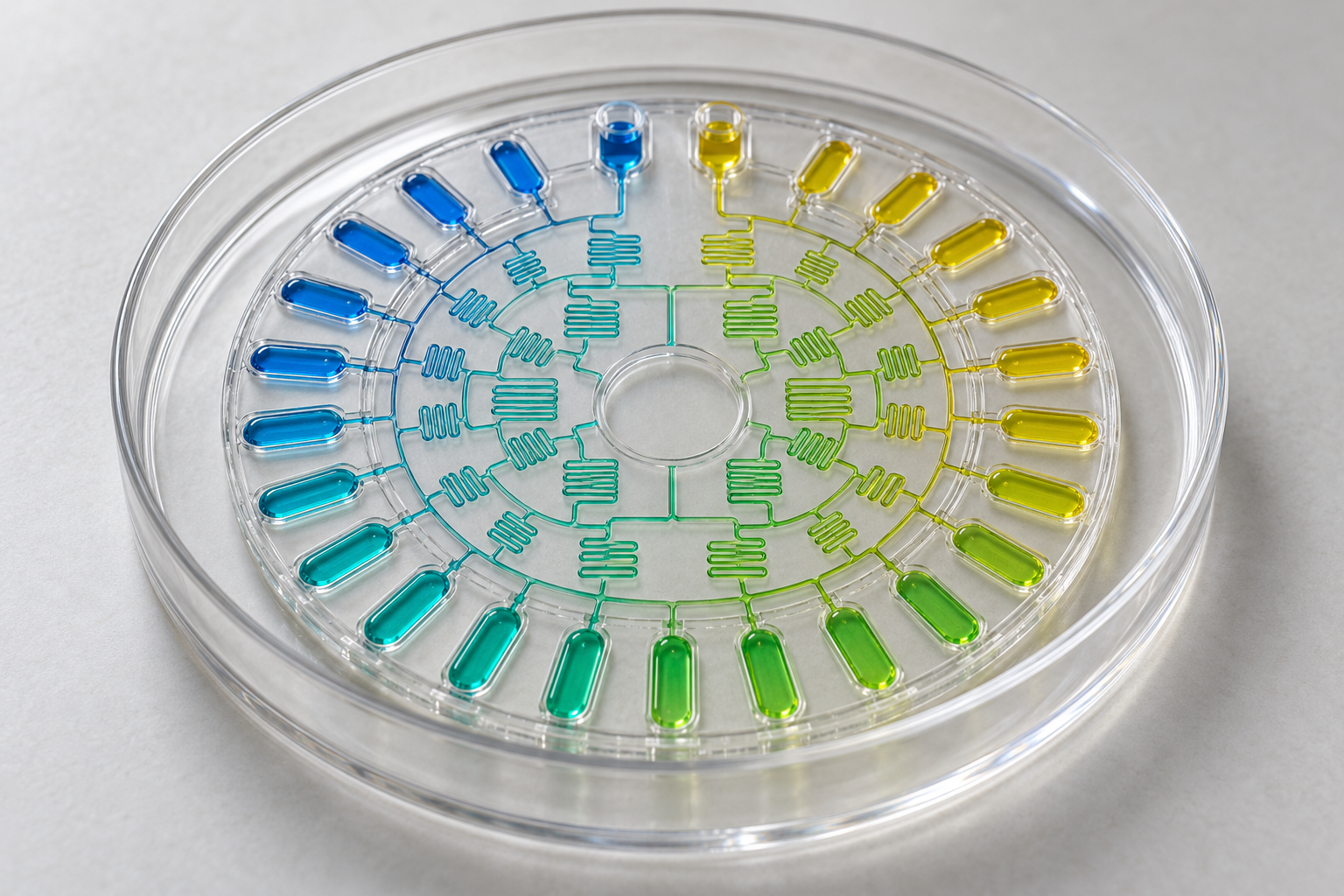
Combination-therapeutic research requires testing how drugs interact across different concentrations. Manual pipette dosing adds repetitive work, while planar culture dishes offer a limited representation of a three-dimensional cellular environment.
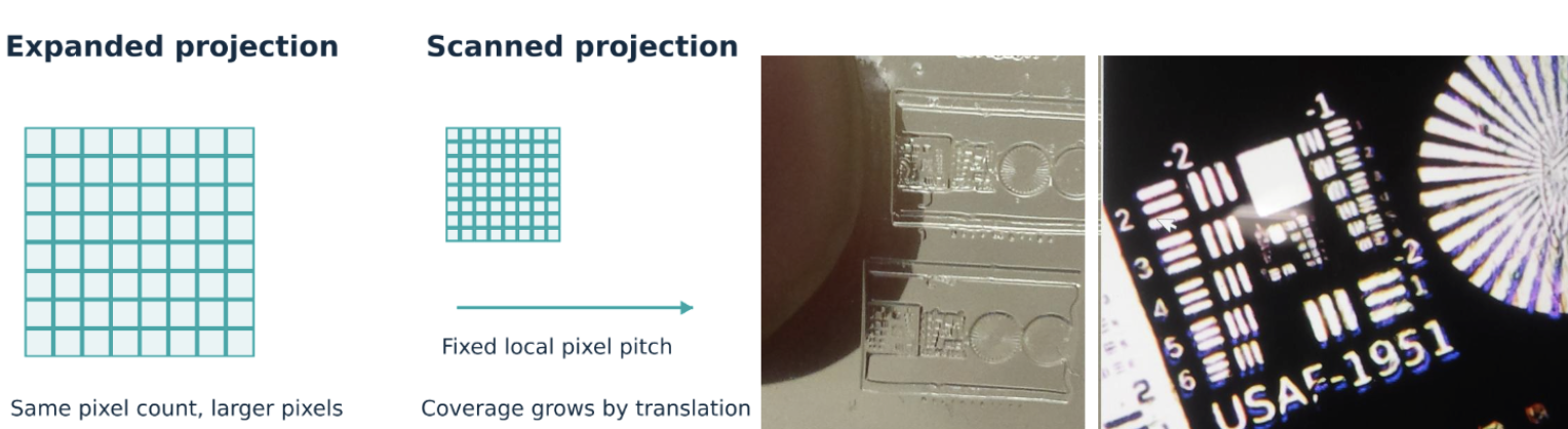
For Evol Sciences, I developed a microfabrication 3D printing system with 4 µm pixels, alongside biocompatible, low-cytotoxicity printing resins for the cell-culture application. The system enabled three-dimensional matrices for studying drug interactions in an environment intended to better reflect aspects of in-vivo conditions than a planar dish.
I also developed microfluidic structures that automatically generated drug-combination gradients in cell culture, replacing manual pipette dosing for that step of the experimental workflow.
The value of additive manufacturing was not simply making a small part. It was using precisely controlled geometry and suitable materials to reduce repetitive dosing work and expand the experimental workflow for combination therapeutics.
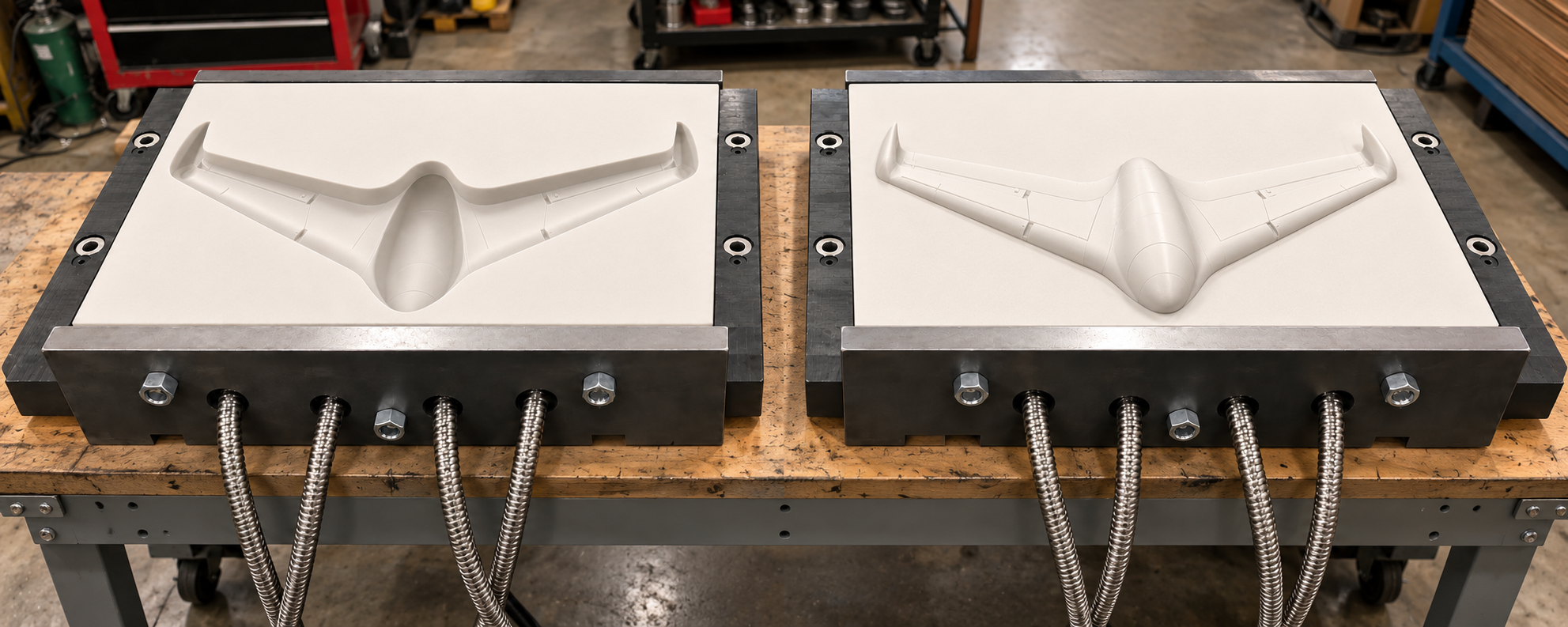
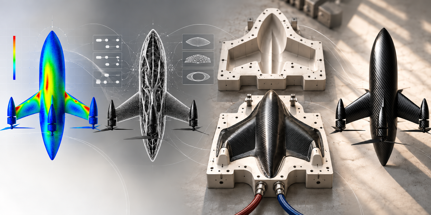
For drone airframes, I examined thermoforming and compression molding of thermoplastic-impregnated carbon-fiber sheets as a route to producing shells in minutes. The production opportunity was compelling, but conventional aluminum tooling introduced substantial cost and lead time between design iterations.
I identified the mold as the bottleneck and developed an approach combining SLA-defined tool geometry, ceramic backing, and a reusable steel frame. The current process targets a three-day fabrication cycle, with an optional metallized face for wear resistance and heat spreading.
Use additive manufacturing to make the tool quickly, then use compression molding to make the parts repeatedly. This preserves rapid design iteration while creating a route beyond direct-printed prototypes to scalable composite production.
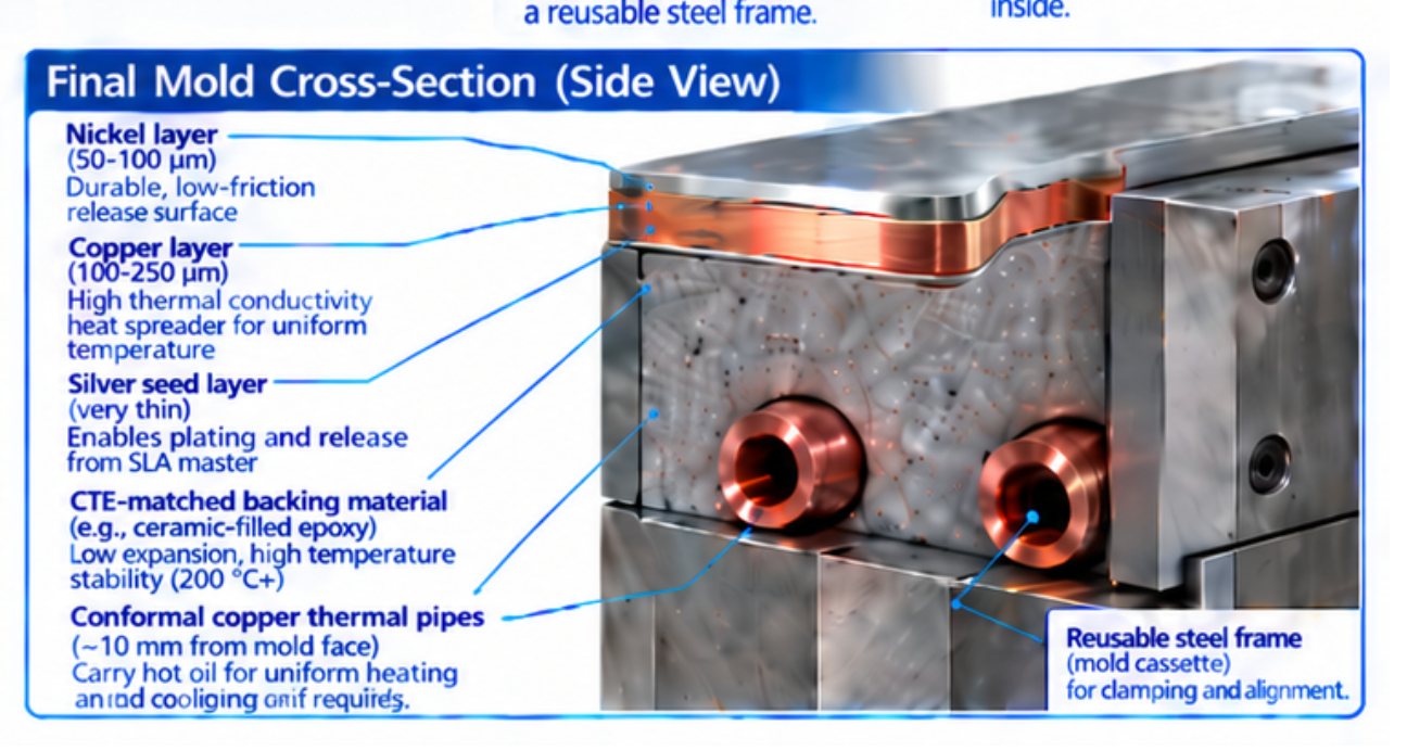
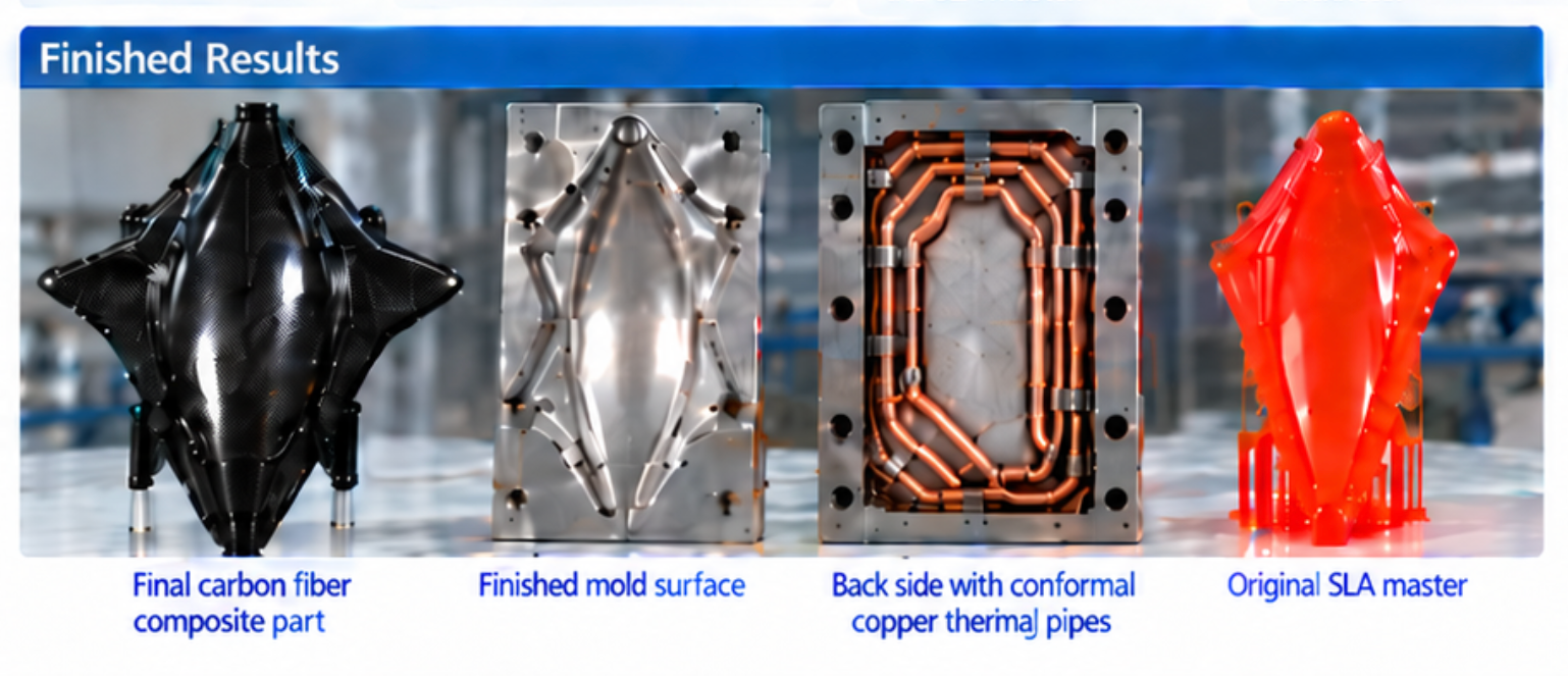
Concept visuals. The cross-section includes a ceramic-filled epoxy backing example; the high-temperature ceramic formulation is a separate material route. Face thickness, adhesion, thermal expansion, and cycle life are application-specific.
SLA shell printing, cleaning, post-cure, and surface preparation. Add a conductive seed coat for the optional metal-facing route.
Install reinforcement and the frame, mix and pour the ceramic backing, then allow the initial room-temperature chemical set.
Controlled staged dehydration and thermal conditioning, followed by cooling and inspection. The schedule depends on the selected chemistry and section thickness.
72-hour development target for the base fabrication route. Optional electroplating, finishing, and qualification may add time. Thermal conditioning is not a blanket claim of ceramic sintering or a validated service-temperature rating.
The planning comparison is a 3-day target against 5–7 days for in-house CNC aluminum or 6–8 weeks for externally sourced steel dies. These are project estimates, not universal supplier lead times.
The preliminary ceramic-route subtotal is $1,990 before SLA costs. Optional plating and final processing scope still need to be priced, so a complete cost-saving percentage is not yet established.
A low-expansion ceramic formulation can help manage tool–part thermal mismatch. Dimensional accuracy depends on the complete material stack, laminate direction, temperature cycle, and tool design.
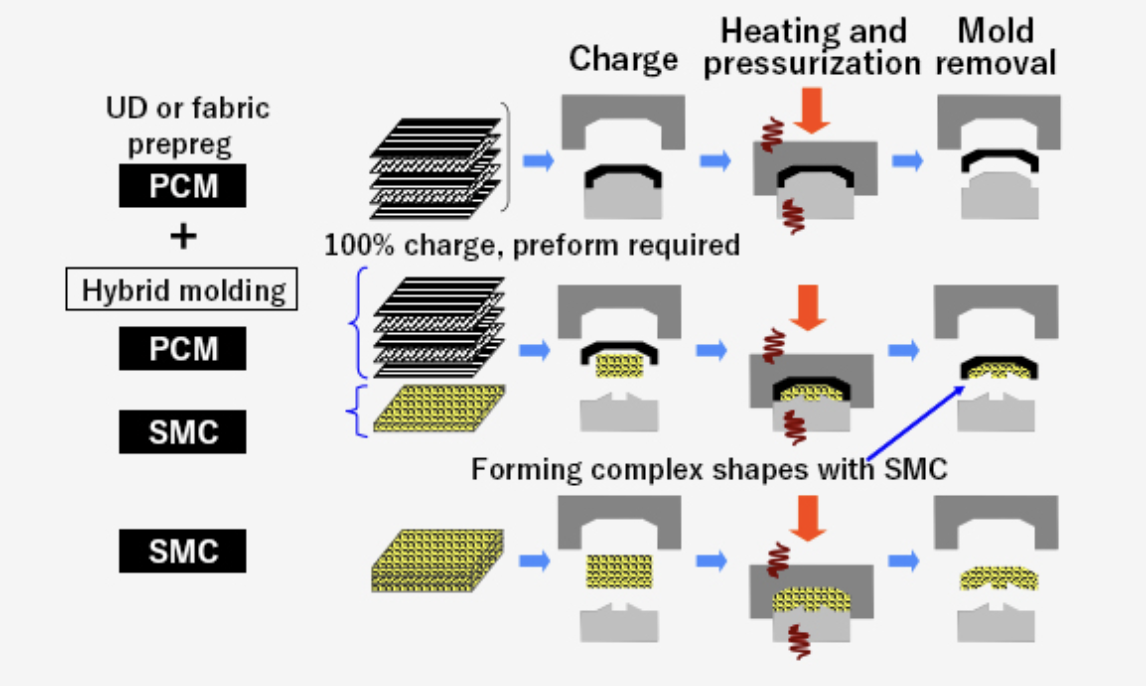
Process references: Electroplating SLA parts · Composite tooling and thermal expansion. Timing and cost estimates supplied by Kurt.
“The output should be a design that can be made—not just a shape that looks convincing.”
AI can accelerate concept creation and customization. Its practical value grows when design freedom is guided by the material, process, and production requirements of the final product.
I build toward workflows that guide customers through intuitive product choices and translate those choices into parametrically controlled designs. Text-to-image, multi-image generation and editing, mesh generation, and AI-assisted CAD become stages in a connected development process.
My design philosophy is to begin with controllable parameters and manufacturing constraints. Tools such as nTop and Metafold are reference points for this approach; the objective is to connect topology and geometry control with rapid, application-specific customization.
Constrain features such as wall thickness, clearances, material behavior, build orientation, and post-processing needs. Review the resulting geometry against the intended process so that each iteration moves toward a production-ready part and a credible path to higher volumes.
High-molecular-weight polymers for footwear: developing printable elastomeric materials around the behavior a shoe needs.
A shoe can call for different responses in different regions. My formulation work explores elastic rebound, energy absorption, and temperature-responsive shape memory, alongside the lattice geometry and printing process used to deliver them.
A printed lattice deforms under compression and rebounds when released.
Explore cushioning and recovery.
A compression demonstration showing the sample’s deformation and recovery behavior.
Explore impact-management behavior.
A demonstration of temperature-responsive shape recovery in a printed polymer sample.
Explore thermally activated fitting and reshaping.
A view of footwear-shaped parts inside the printing system from my presentation.
Connect formulation, geometry, and process.
Formulation + lattice + process
Material behavior is part of the design. I consider the polymer formulation, internal structure, and manufacturing method together to develop the intended footwear response.
Qualitative demonstrations from my presentation. These clips illustrate material behavior; they are not standardized mechanical tests or comparative performance measurements.
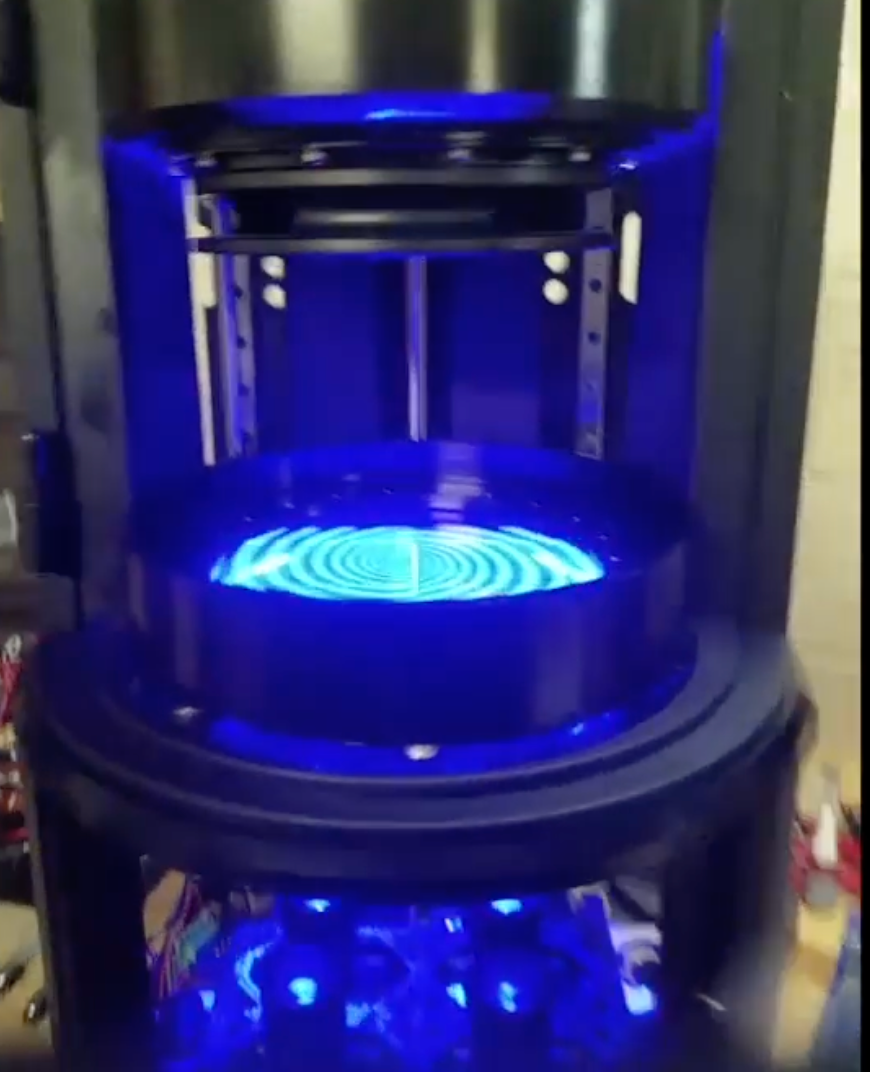 ORANGE MAKER / MACHINE ARCHIVE
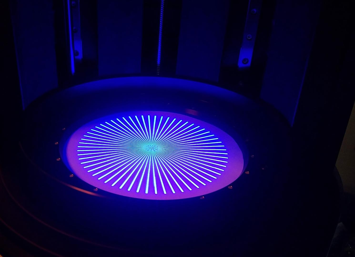
This is one of my top-down, multi-DLP 3D printing systems. It combines projected exposure with a rotating build plate to support printing dense parts.
Developing systems like this connects optics, motion, materials, and process control. The goal is to make useful geometries and material applications practical—and turn that capability into a repeatable manufacturing workflow.
Actual machine image supplied by Kurt Dudley.
Help an idea become a real product—and develop the design and manufacturing strategy that allows it to reach more people.
Identify the need, explore the opportunity, and develop the tools or processes that unlock it.
Turn the concept into a functional, manufacturable design through focused development and iteration.
Connect tooling, automation, materials, and production methods to the demands of growing volume.
Application engineering, DFAM, advanced materials, and automation—brought together around what you need to make.
Explore my services ↗My passion for additive manufacturing has always been about enabling people to make things.
Through Orange Maker and my consulting work, I have focused on expanding the range of useful things people can produce efficiently. That means developing printing systems, application-specific materials, optimized processes, and approaches to automated post-processing.
The AI era opens another part of that mission: making design more accessible. Manufacturing knowledge can be built into intuitive workflows that help a customer explore an idea, customize it, and arrive at something that can be made cost-effectively today.
I continue to develop this toolset and learn across disciplines so I can help inventors, designers, and companies make their ideas real and bring them to market. I’m looking for a full-time role where I can contribute this experience across design, application engineering, and scalable manufacturing, while continuing to support selected consulting projects.
Explore how my experience can support your next product, manufacturing challenge, or team.